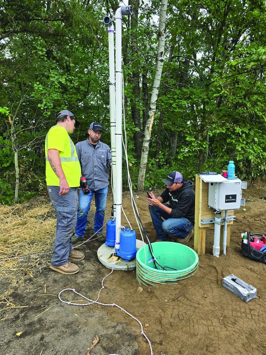
There’s a lot that goes into setting a new pump or replacing floats in onsite water treatment systems.
First, the service provider needs to know the gallons per inch of the dosing tank, which the tank manufacturer typically provides, but can also be calculated using the area of the tank.
Next, is understanding the sensors involved. The sensors used with dosing tanks are adjustable and each has a specific function. The most common are float controls tethered to a float tree and suspended at specific elevations within the tank. Since the pump must always be covered with liquid, the first determination is the off value of the float. This is calculated by measuring the pump height including a block and adding 2 inches to cover the pump. That height is then multiplied by the gallons per inch to calculate the volume. This capacity is lost as part of the dosing, since effluent must always cover the pump.
On-float value
To determine the on-float value you must know the dose volume. Referring back to the design documentation will hopefully provide this information, but if not here are some items to consider.
First, you never want to overload the system, and many regulations cap a dose to a soil treatment area at 25% of the design flow. For instance, if you had a 600 gpd system, the start and stop levels should be set to pump no more than 0.25 x 600 gpd = 150 gallons per dose.
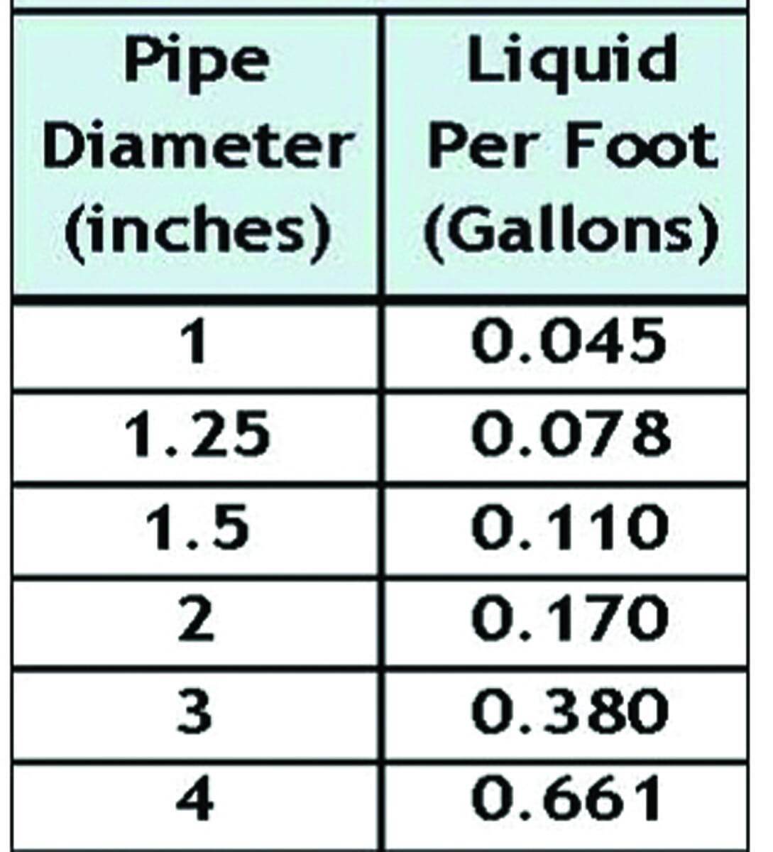
For pumping to pressure applications, the same rule applies that the dose should not be greater than 25% of the design flow, but also must be large enough to deliver an appropriate dose once the pipe is full of effluent and pressurized. A common rule of thumb is four to five times the volume of the distribution pipes to allow a reasonable pump operation time. The volume of effluent required to fill the laterals can be calculated using the chart to the right.
For example, if the STA has three laterals 1.5 inches in diameter with a length of 37 feet the volume would be:
- 3 laterals x 37 feet x 0.110 gallons per foot = 12.2 gallons to fill laterals
- Four times that volume would be your minimum dose:
- 12.2 gallons to fill laterals x 4 = 48.8 gallons
Other considerations
Many pumping applications are designed to drain the supply line up to the system back to the dosing tank, so this volume will need to be added onto your minimum dose. Then the total amount of drainback is calculated by multiplying the length of pipe in feet times the volume of the liquid per linear foot.
You also want to consider the manifold impact upon drainback. This is determined by the style of manifold-to-lateral connections. In staggered tee connections, the manifold drains through the holes. In tee-to-tee connections, the manifold drains back to the dosing chamber. Check valves are sometimes used on very long mains to eliminate the need to drain and refill them. In this case, the dose volume will have no drainback volume added. However, mainlines with check valves must be protected from freezing.
The dose volume must be between the volume of the supply line plus four to five times the volume of the distribution piping (at a minimum), and 25% of the design flow (at a maximum) and adding on drainback if this is part of the system configuration.
Dosing
A pump system can be dosed either when a set volume is collected (demand dosed system) or by using pump capacity (gpm) and time (time dosed system).
Demand-dosing is a common mode for delivering effluent to the final treatment and dispersal component. Timers are more commonly found on pretreatment devices or systems requiring flow equalization.
If demand dosing is used where the floats alone control the pump, the float separation distance is calculated by taking the dose volume divided by the gallons per inch of the tank. The alarm depth then needs to be determined.
Typically, the alarm is triggered when the effluent gets 2-3 inches above the pump start level. To determine this volume, choose an alarm depth and multiply by the gallons per inch. The alarm volume along with the volume to cover the pump and dose volume to determine the total working volume. The depth above this is reserve capacity in case of issues with the pump.
Therefore, the on/off float will be set to cover the pump (off) and then the on-float height will be based on the dose volume. The alarm float height is then the distance to set the pump-on float plus the alarm depth.
Timing it
When a timer is being used to control the pump the gallons per minute of the pump being used must be defined.
In most instances, this will come from the pressure distribution design, but also may be chosen in gravity applications. During installation or on existing systems, the gpm must be calculated by performing a draw down test where the change in depth in a tank in inches is recorded over a period of time and multiplied by the gallons per inch of the tank. This is the only way to have an accurate dose.
Once the gpm is known, to calculate the “timer on” setting, the dose volume is divided by the gpm of the pump. This will provide the number of minutes the pump will run each time it turns on. The pump will not be activated if sufficient sewage is not present to be dosed. To determine the “timer off,” take the number of minutes in a day (1,440) divided by the likely or measured doses per day and subtract the timer on value. This will establish the amount of time between doses in minutes. This may need to be adjusted over time if current usage per day is unknown.
During pump repair and replacement in time dose systems, the actual flows should be considered when setting the on/off times to ensure the flow is being equalized as planned to maximize performance. The pump-off float is still set to cover by taking the gallons to cover the pump and dividing by the gallons per inch of the tank.
Setting these floats properly based on system design and components is critical to ensure the dosing system is delivering the required effluent.
Continue reading for free