Proper installation of a pump and discharge assembly requires three specific features to assure the pump will work properly and be serviceable. It must be:
- accessible
- replaceable
- properly controlled
Accessible
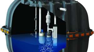
The pump, pump controls and pump discharge line must be installed to allow access for servicing or replacement without entering the pump tank. Accessible means that the pump is underneath the manhole. It should be noted that the access manhole should be brought to the surface; the pump will need maintenance at some point, and if the manhole is not at the surface, what could be simple becomes complicated each time service is necessary. The pump should be placed directly below this manhole.
The pump should have a quick disconnect as part of the pump assembly. This quick disconnect allows for the quick and easy removal and reinstallation of the pump, which should be able to be accomplished with little to no need for significant tools. A cordless Sawzall is not considered a quick disconnect but can be very useful for fixing other minimal installations. A Fernco (a rubber piece with two hose clamps) is useful for gravity installation but is not a quick disconnect; it is an automatic disconnect. A Fernco is not designed for pressure greater than 7 to 10 feet of head. Even a pressure Fernco doesn’t allow for typical pressures in a pressure system.
A final factor in pump accessibility is that the pump assembly is reachable from the surface. Typically, this means 18 to 20 inches from the access lid to the piping for removal of the pump. It is also helpful if the pump has a rope for assisting in the removal of the pump. This will make it easier for the pump to be lifted and replaced.
Replaceable
The pump and controls should be replaceable. For the pump, this means that it is accessible as described above, as well as removable from the tank. Removable means that the pump wiring can be taken out without significant excavation. The wires should run through a conduit. Chipped concrete is not a good conduit for the wires entering and exiting the tank. The conduit should be large enough to allow for any plugs to be pulled through the conduit and the box. It is important to remember that if the plug is removed from the pump, the warranty is typically voided. Make sure that all wiring meets all applicable state and national electrical standards. It’s also helpful to have the pump floats on a separate float tree. This allows for the removal of the pump without removing the floats, and vice versa. The use of a float tree will ensure quick access and removal when necessary.
The pump should also be elevated 3 to 4 inches off the bottom of the tank. The elevation protects the pump and downstream components from solids that can accumulate in the bottom of the pump tank. When doing this, use enough blocks so that you can replace the pump from the surface. A single block at the bottom of the tank will not be sufficient: trying to balance a half- horse pump on the end of an 8-to-10-foot section of 2-inch pipe can be a very difficult job. Adding several bricks to give a wider base is helpful and will not negatively impact the system.
Properly controlled
The sensors that activate the pump and alarm are typically float switches. Other devices are also used, such as pressure transducers and ultrasonic water level sensors. The sensors are adjustable, and each is set to operate specific components in the tank.
The most basic form of demand dosing is a float-operated, motor duty switch into which the pump is plugged. The float is a single wide-angle or differential float control and the configuration is usually called a “piggyback control.” Although still specified and used in some areas, this configuration provides no information on system performance if meters or counters are not included. Meters and counters can be temporarily wired into the panel for troubleshooting purposes. If the system has only piggyback controls, an upgrade to a control panel should be strongly recommended to facilitate data collection during operation and maintenance over the course of system use. Certainly, a high-water alarm float switch should be wired into the panel to signal excessive hydraulic loading or pump failure.
Meeting these requirements — accessibility, removability and control — will alleviate many problems that could be experienced with pump systems and will make the pumping system easier to maintain.
About the author: Sara Heger, Ph.D., is a researcher and educator in the Onsite Sewage Treatment Program in the Water Resources Center at the University of Minnesota, where she also earned her degrees in agricultural and biosystems engineering and water resource science. She presents at many local and national training events regarding the design, installation and management of septic systems and related research. Heger is the President of the National Onsite Wastewater Recycling Association and she serves on the NSF International Committee on Wastewater Treatment Systems. Ask Heger questions about septic system design, installation, maintenance and operation by sending an email to kim.peterson@colepublishing.com.
Continue reading for free