Interested in Onsite Systems?
Get Onsite Systems articles, news and videos right in your inbox! Sign up now.
Onsite Systems + Get AlertsAny onsite septic system will begin with a design/plan. Every installation should begin with a careful review of the plan for that system. A site plan is a graphical representation of existing natural and manmade physical features that are present at the site and those that are proposed to be installed or changed.
All components of the proposed septic system should be drawn on the plan. Distances from the components to existing features and property lines should be indicated on the plan so the installer can build or assemble the components as the plan proposes. The installer can use the details on the site plan to get a sense of what machinery to use, where to stockpile materials, and the general logistics for construction staging.
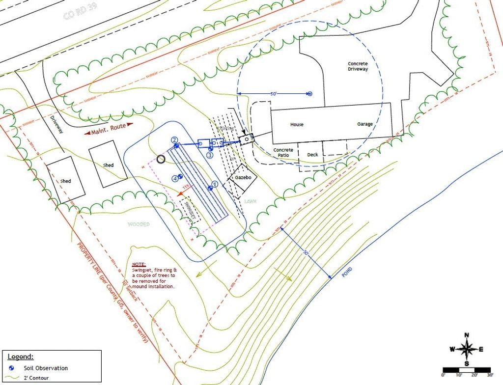
Most septic system designed are provided in plan view as shown above. The plan view shows the relative horizontal position of the surface features in a bird's-eye view. Several items need to be included in a plan view that will be used to install a septic system, including property lines and existing structures. The north arrow is another important feature on the site plan. Used with the location map, it helps the reviewer get oriented. It typically, but doesn't always, point to the top of the design plan sheet.
Topographic plans show variations in elevation of the land and the relative position of natural and manmade physical features. These represented variations of the land surface are shown as they appear on the site and may also show proposed changes in elevations of the ground surface. The elevation of a point in the landscape is the height of that point relative to a fixed point of known elevation. Topographic plans show contour line intervals depending on the scale of the plan and the slope of the landscape. For onsite wastewater treatment system site plans, the contour is typically 1 or 2 feet.
Topographic plans are useless without a benchmark. A benchmark is a fixed point of known elevation at a comfortable distance from the construction area. The benchmark should be in a location in which the elevation can be easily transferable by the installer. Without a benchmark, the installer cannot accurately set elevations at the site. Benchmarks are referenced to a national or local datum or are more commonly an assumed elevation. An assumed elevation can be arbitrarily set by the person conducting the site evaluation.
Topographic plans can also be used by an installer to collect information such as slope. The slope is the relative incline of a surface or the amount of deviation from the horizontal. The slope in the parcel of land might be relatively flat or steep. The relative closeness of contour lines gives a sense of the slope. In general, depending on the scale of the map, when the contours are close together on the plan, the slope is generally steep. When the contours are spaced out, the slope is mild.
The installer should consider the following when evaluating the contour and slope as shown by the site plan:
- The effects of topography on surface and groundwater flow.
- Water will run perpendicular to the contour lines, just as the direction of the downward slope.
- If the soil treatment area is located at the bottom of a concave type landscape, the design plan should also address precautions that need to be in place to route surface water around the system such as berms and swales.
- The installer should keep in mind that groundwater also moves toward a common area in concave slopes and can raise the seasonal high groundwater table in these areas relative to the rest of the site. When excavating in these areas, the installer must be careful in assessing if the seasonal high groundwater table agrees with the site and soil evaluation report.
- Slope calculations involving intersection of existing slopes to proposed slopes in cuts or fills (if cut and fill is allowed in the jurisdiction). Existing contours are typically shown as dashed lines, whereas proposed contours are shown in solid continuous lines. Cuts show a solid contour line of less elevation drawn in the direction of a contour line of greater elevation. The opposite is true for areas of proposed fill.
An installer must be familiar with design plans for the construction of onsite wastewater treatment systems. The level of detail of the plan varies with jurisdiction. No matter what level of detail is typical for an area, the installer should be aware of whether a plan they are reviewing has been approved for construction by the relevant jurisdiction.
About the author: Sara Heger, Ph.D., is a researcher and educator in the Onsite Sewage Treatment Program in the Water Resources Center at the University of Minnesota, where she also earned her degrees in agricultural and biosystems engineering and water resource science. She presents at many local and national training events regarding the design, installation and management of septic systems and related research. Heger is the President of the National Onsite Wastewater Recycling Association and she serves on the NSF International Committee on Wastewater Treatment Systems. Ask Heger questions about septic system design, installation, maintenance and operation by sending an email to kim.peterson@colepublishing.com.