
Filed Under
Sign Me Up!
Sign up Digital!
Subscribe to Print!

Interested in Trucks?
Get Trucks articles, news and videos right in your inbox! Sign up now.
Trucks + Get AlertsSeptic pumpers who are branching out into onsite installation and maintenance often work off the designs of others. As educators, we often hear them say, in effect, “I don’t need to know that because I can follow the plan — that’s the designer’s job.” Nowhere is this more common than in selecting the right pump for a system.
While a good designer will account for the necessary design elements and will have the “right” answer, everyone installing a system with pumps should understand how that pump was selected. That way, the installer will understand how any changes made during the installation will affect the pump. (And we know that changes happen.) This is all the more critical for installers who also work on repairs and troubleshooting.
Getting the basics
The right pump for the job is determined by the conditions at the site and by the reason for the pump. Every pump has a distinct operating curve based on the amount of water that needs to be delivered (in gallons per minute, or gpm) and the total dynamic head (TDH, in feet) that the pump must overcome to send effluent where it needs to go.
If the pump needs to move septic tank effluent to a drop box at a higher elevation, from which it will flow by gravity to the trenches, it needs to deliver at least 10 gpm and no more than 45 gpm at the drop box.
The minimum ensures that the pump will run fast enough to keep ahead of appliance discharges from washing machines and dishwashers. The maximum ensures that effluent has time to flow by gravity out of the drop box to the soil treatment system.
In this flow situation, TDH is determined by adding the elevation difference from the pump to the drop box and calculating the friction loss in the supply pipe to the distribution box. You can then visit the pump supplier and ask what effluent pumps are available that operate within those delivery and hydraulic head requirements.
If the pump will send effluent to a pressure distribution system, you still need to determine the delivery and head requirements, but the process is a bit more complicated. The number and size of the perforations (orifices) in the pressure distribution system will determine the required pump capacity.
The flow required to pressurize the laterals is the volume and pump capacity needed to force effluent evenly out of the orifices. That volume is the amount of liquid needed to fill the laterals and is set by the dose volume to the laterals. The pump capacity is based on the orifice diameter (typically 1/8- to 1/4-inch) and the number of orifices in the system.
The second component of this calculation is the minimum pressure delivered at each orifice. The higher the pressure, the more flow is typically needed, but the harder it will be to plug the system. This is critical, because as pump capacity (rate of flow) increases, friction loss becomes greater. Both of these directly affect pump size and cost.
Be careful in designing or changing the pressure distribution system. Be sure to correlate any changes you make in the field to the pump sizing components. Changing the number of orifices, or making them larger (even if by poor drilling practices), will increase the flow and the required pump capacity.
One pump option is the effluent turbine pump from Clarus Environmental. Pumps are available in capacities from 11 to 85 gpm, with heads up to 500 feet. Pumps range from 1/2 to 3 hp.
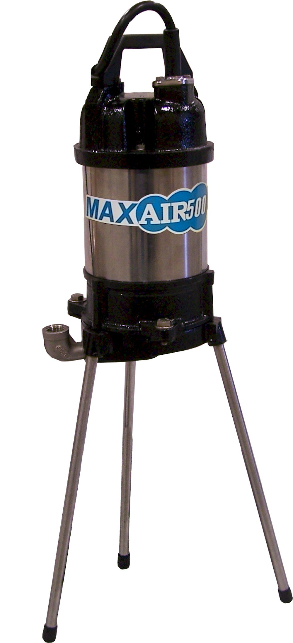
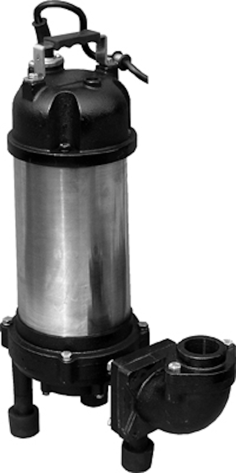
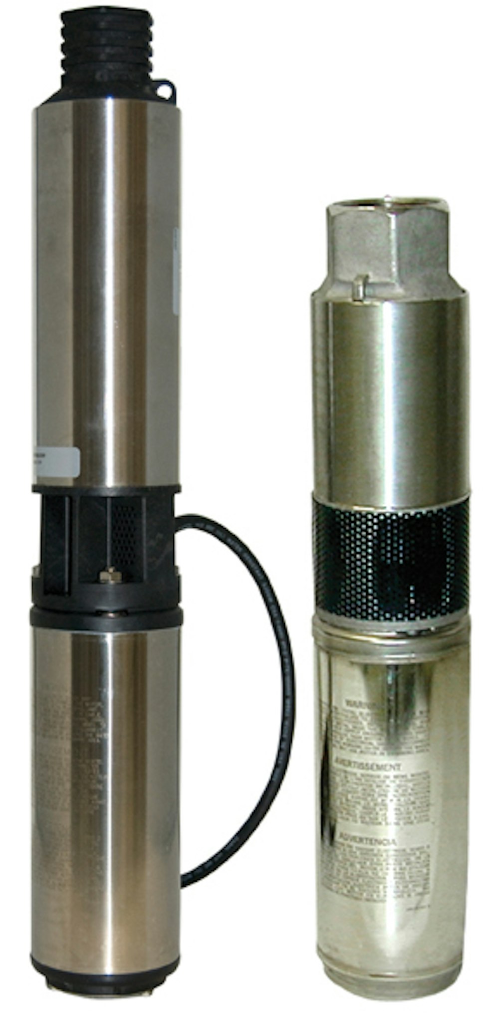
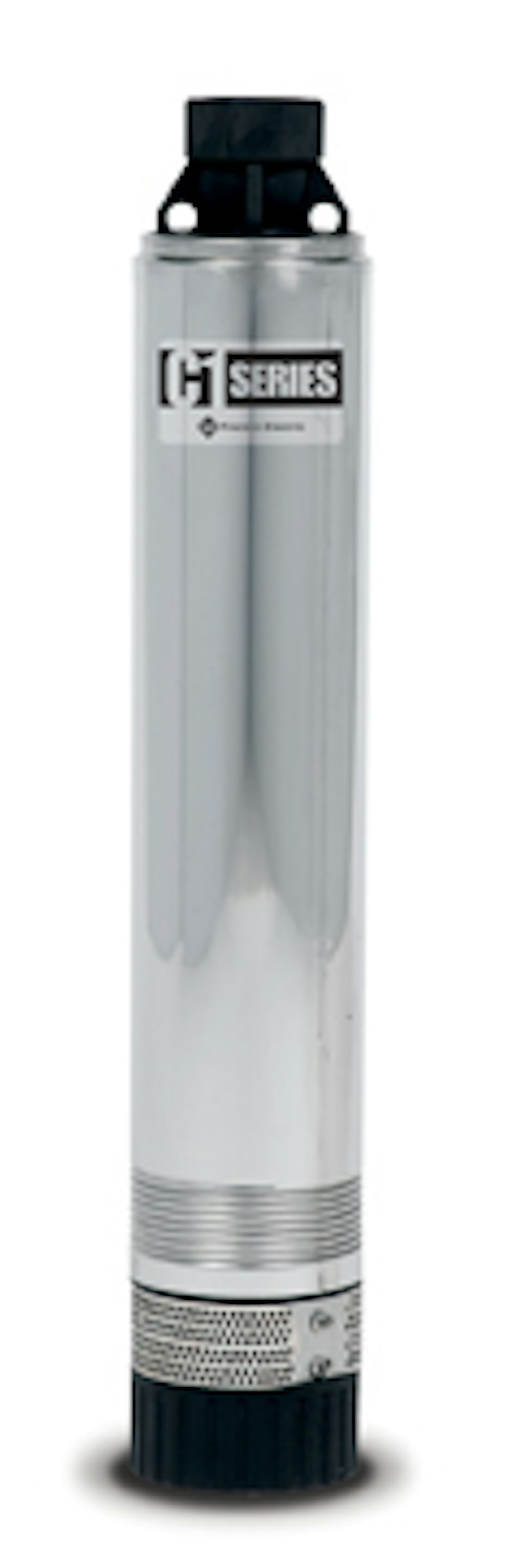
C1 Series stainless steel submersible cistern pumps from Franklin Electric are used in graywater/filtered effluent septic system applications, and pass solids up to 1/8 inch in diameter without impacting pump life.
The InviziQ pressure sewer system uses grinding and pumping to move sewage efficiently to treatment facilities regardless of the terrain, slope, environmental sensitivity or topography.
Calculating head
To determine the head requirement, you must calculate or estimate three components. The first (typically largest) is the elevation difference. Here, you simply measure the vertical distance (in feet) from the top of the pump in the pump chamber to the discharge point — the elevation of the discharge laterals.
The second component is the friction loss in the supply pipe and laterals. Friction loss is a function of the size of the pipe and the effluent flow velocity. The smaller the pipe, the more friction loss. The more that flows through the pipe, the more friction loss.
The friction loss in the supply pipe also includes the unions or other fittings that connect to the pressure manifold. You can calculate the loss for each fitting, or make a rule-of-thumb estimate by adding 25 percent to the friction loss of the pipe.
The third component of friction loss covers losses in other components of the pressure system, such as a splitter valve or other valves. You should add friction loss for the pressure distribution piping — typically calculated at an additional 5 feet of head if using 2-inch piping. (If the distribution manifold will be smaller, then the friction loss in the distribution manifold may be a little bit greater.)
For instance ...
Let’s look at a quick and simple example. The pressure distribution laterals for a mound system with a 10- by 40-foot rock bed has about 40 perforations. If each of these perforations is 1/4 inch in diameter, you need capacity to deliver 40 gpm to pressurize these orifices. The TDH for the system is determined by measuring:
- The elevation difference from the pump to the pressure distribution system.
- The friction loss in the pipe and fittings.
- Special components in the distribution system.
In the backyard, we measure that the elevation difference is 14 feet. There is 80 feet of 2-inch Schedule 40 supply pipe. The friction loss in this pipe, determined from a friction loss table, is about 3 feet per 100 feet. Adding 25 percent for friction loss in the fittings, the friction loss in the whole pipe would be approximately 3 feet of head.
The final head requirement is the loss in the distribution network and any additional losses in the system. A design value of 5 feet of head is used for typical mound pressure distribution laterals.
The total head requirement for this system is the sum of these pieces:
- 14 feet for the elevation
- 3 feet for the pipe and fittings
- 5 feet for the distribution system
That totals 22 feet of head. The pump required for this system needs to be able to deliver 40 gpm at 22 feet of total dynamic head. If the pump cannot do this, the pressure distribution system will not work as designed. On the other hand, if the pump is sized to do much more, it is probably more expensive than necessary.
Also consider the other non-system-related issues in pump selection. Service, warranty and price, for example, may play a role. Choosing the right pump is critical if you want to install systems that work the way they’re supposed to, enabling long-term performance in treating wastewater.
Need more options? We put together this list to satisfy all your pumping needs:
- The 2 hp grinder pump from Champion Pump provides up to 133 feet TDH option.
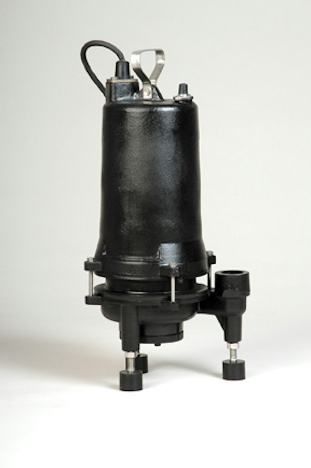
- The MAXAIR500 submersible aerator from Septic Services features corrosion-resistant stainless steel legs with thick rubber feet to provide added stability.
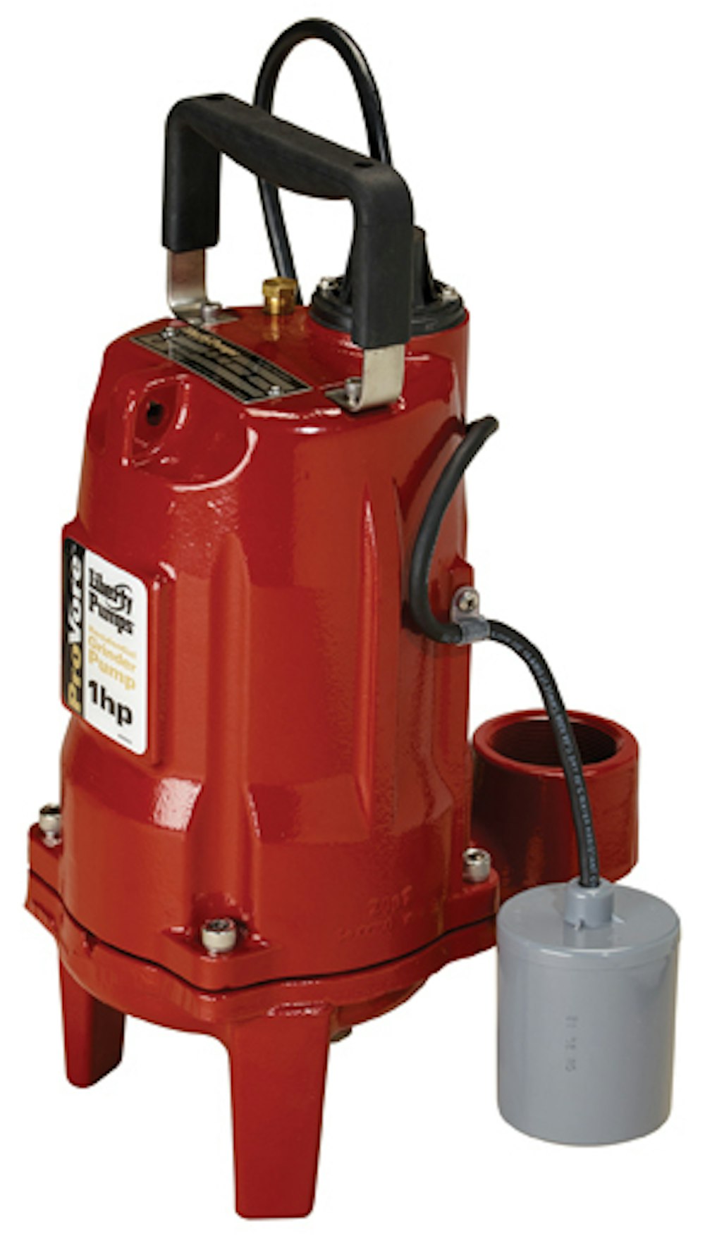
- The ProVore grinder pump from Liberty Pumps is designed for use in residential applications where the addition of a bathroom or other fixtures below sewer lines requires pumping.
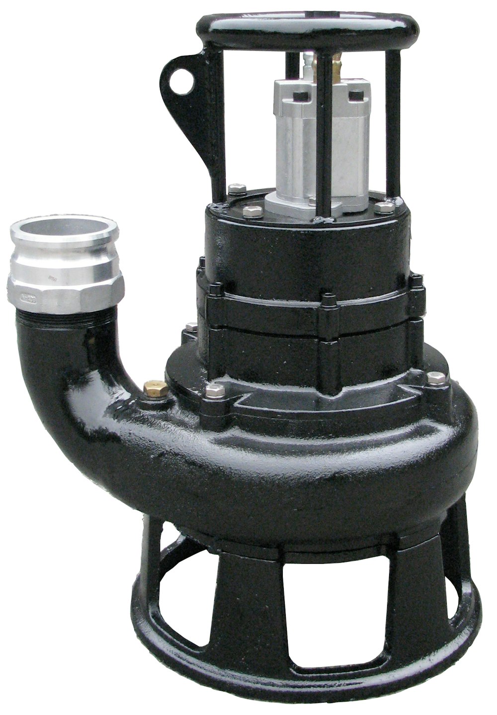
- The S4SHR 4-inch hydraulic submersible shredder pump from Hydra-Tech Pumps is designed to continuously rip and shear solids with a 360-degree shredding action.
- MVP Series grinder pumps from Weber Industries — Webtrol Pumps are constructed from Type 304 stainless steel and cast iron.
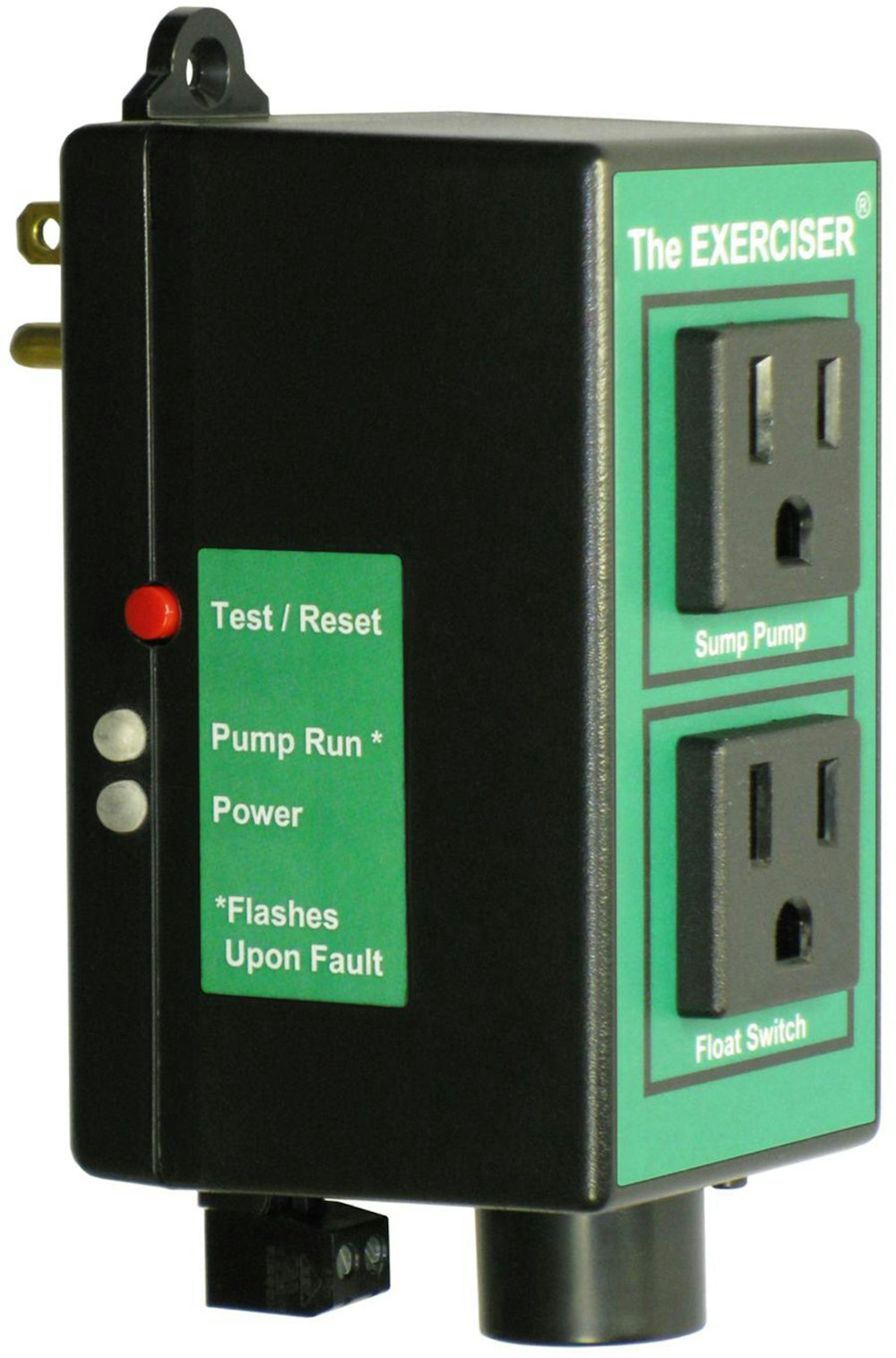
- The Exerciser from Motor Protection Electronics is designed to exercise a sump or sewage pump that may sit dormant for extended periods of time.
Want to learn more? Check out complete product listings and manufacturer contact information.
About the Authors
Jim Anderson and David Gustafson are with the University of Minnesota’s widely recognized onsite wastewater treatment education program. Anderson is director of the university’s Water Resources Center and Gustafson is the university’s extension onsite sewage treatment educator. Readers are welcome to submit questions or article suggestions to them at ander045@umn.edu.